

2022 DMG MORI NLX2500SY/1250 long bed with milling !
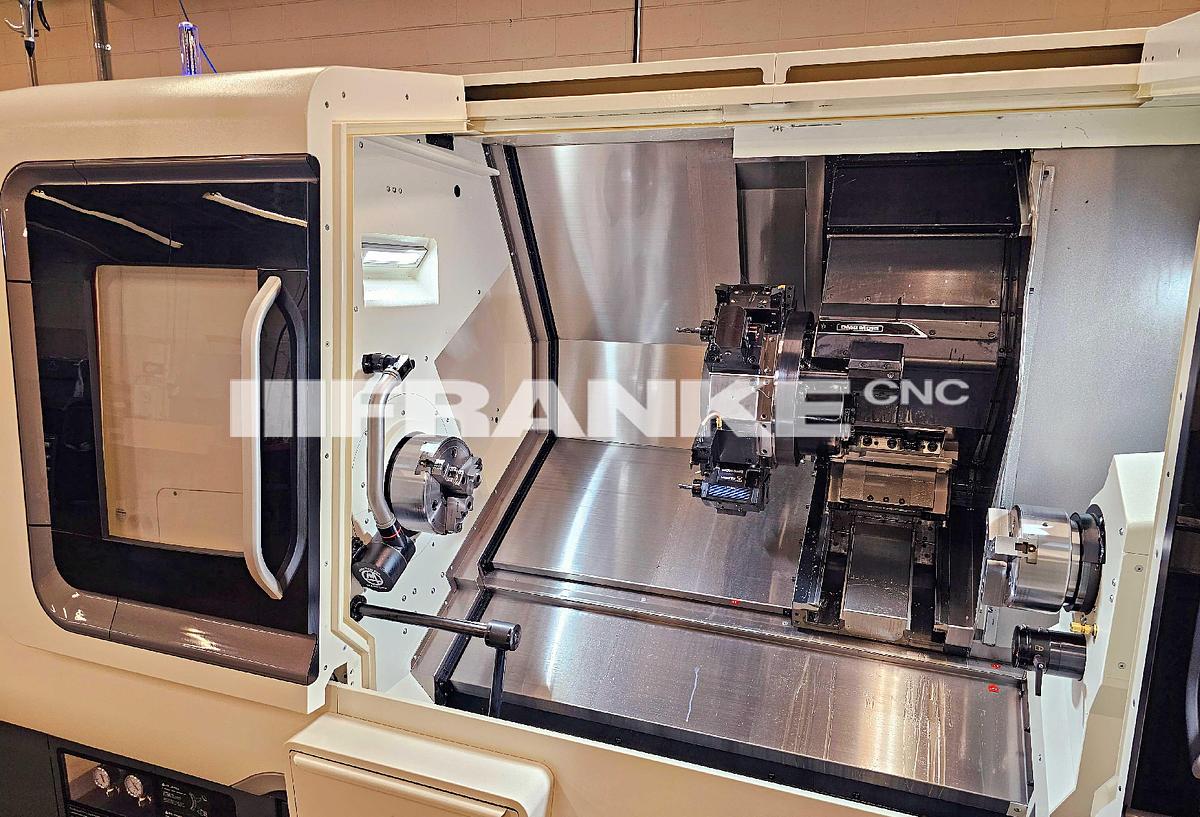
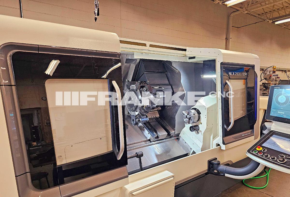
2022 DMG MORI NLX2500SY/1250 long bed with milling !
Description
Basic Machine
NLX 2500 | 1250 - Milling Specification J-A01440* 1
Control
Control M730UM with CELOS (NLX2500) Control unit: Mitsubishi M730UM J-006140* 1
Operation system: CELOS (MAPPS V)
CELOS - ERGOline Touch J-003261* 1
It is a machine operation panel with 21.5-inch multi
touch screen, which realizes comfortable operability. It documents, visualizes and centrally
manages the order, process and machine data,
allowing the networking with CAD/CAM and also
the function extension using applications. The
user-friendly, highly-productive MAPPS system is installed.
Spindle
(Left Spindle) High-Output Spindle 26/26/22 kW, J-016102 1
4,000 min-1
The NLX 2500 adopts a highly reliable spindle
designed to minimize thermal displacement. The
advanced spindle labyrinth structure and the spindle air purge adopted for the machine (option
for the 2-axis turning specification) achieves the
highly durable spindle by preventing coolant from
entering the spindle.
Max. spindle speed: 4,000 min-1 Spindle nose type: JIS A2-8
Through-spindle hole diameter: Φ 91 mm
(dia.3.58 inch.)
Min. spindle indexing angle: 0.001°
Spindle drive motor: 26/26/22 kW (34.7/34.7/30
HP) (25% ED/50% ED/cont)
Spindle torque: 709/500/409 Nm
(522.93/368.78/301.66 ft·lbf) (10 min/30 min/cont)
(Right Spindle) Standard Spindle 11/7.5 kW, 6,000 J-016151 1
min-1
The Right Spindle specification enables
continuous machining of both surfaces. The
combination of rotary tools and the Y-axis function
enables integrated machining from turning to secondary/back face machining, and multi-axis
machining, allowing for process integration.
Right Spindle max. speed: 6,000 min-1
Spindle nose type: JIS A2-5
Through-spindle hole diameter: Φ 43 mm
(dia.1.69 inch.)
Min. spindle indexing angle: 0.001°
Spindle drive motor: 11/7.5 kW (15/10 HP) (25%
ED/cont)
Spindle torque: 77.8/53.1 Nm (57.38/39.16 ft·lbf)
(25% ED/cont)
Chuck for Left spindle (Main spindle)
(Left Spindle) KITAGAWA 10-inch Hollow Chuck J-013368 1
BR10A821
Three-jaw hydraulic chuck manufactured by
Kitagawa Iron Works.
Chuck outer diameter: Φ254 mm (dia.10 inch.)
Through-hole diameter: Φ81 mm (dia. 3.18 inch.) Gripping diameter: Max. Φ254 mm (dia.10 inch.),
Min. Φ31 mm (dia.1.22 inch.)
Jaw stroke (diameter): 8.8 mm (0.35 inch.)
Plunger stroke: 19 mm (0.75 inch.)
Max. allowable pull force: 49 kN (11.01 klbf) Max. static gripping force: 123 kN (27.64 klbf)
Dynamic gripping force at max. speed: 44 kN (9.88
klbf)
Max. allowable speed: 4,500 min-1
Mass: 40.9 kg (89.99 lb.)
*The data above are information on the chuck body. Since it may be limited by this machine
specification, please check the contents of the
mounted cylinder set for details.
(Left Spindle) Hollow Cylinder Set for KITAGAWA J-013383 1
10-inch) Hollow Chuck BR10A821 (Bar work capacity dia. 80 mm (3.15 inch)) (Without Chuck
Body)
Hollow cylinder and draw bar are included as a
set. Chuck is not included. Please see the
chuck-cylinder combination diagram for the
combination with chuck and the specification.
* further description see attachment
Chuck for Right spindle (Counter spindle)
(Right Spindle) KITAGAWA 8-inch Hollow Chuck BR08A521 J-013420 1
Three-jaw hydraulic chuck manufactured by
Kitagawa Iron Works.
Chuck outer diameter: Φ210 mm (dia.8.27 inch.)
Through-hole diameter: Φ66 mm (dia.2.6 inch.)
Gripping diameter: Max. Φ210 mm (dia.8.27 inch.), Min. Φ22 mm (dia.0.87 inch.)
Jaw stroke (diameter): 7.4 mm (0.29 inch.)
Plunger stroke: 16 mm (0.63 inch.)
Max. allowable pull force: 32 kN (7.19 klbf)
Max. static gripping force: 99 kN (22.25 klbf) Dynamic gripping force at max. speed: 33 kN (7.42
klbf)
Max. allowable speed: 5,000 min-1
*The data above are information on the chuck
body. Since it may be limited by this machine
specification, please check the contents of the
mounted cylinder set for details.
(Right Spindle) Solid Cylinder Set for KITAGAWA J-013427 1
8-inch Hollow Chuck BR08A521 (Without Chuck
Body)
Solid cylinder and draw bar are included as a set. Chuck is not included. Please see the
chuck-cylinder combination diagram for the
combination with chuck and the specification.
Options for Turret
Turret Y-axis Specification J-016110 1
It moves the turret in the Y-axis direction. In combination with the rotary tool spindle and right
spindle, it implements process integration for
workpieces with complicated shapes. Please refer
to the turret interference diagrams for the movable
region.
Travel: ± 50 mm (± 1.97 inch.)
Rapid traverse rate: 10 m/min (393.7 ipm)
High-Torque Rotary Tool Spindle 40/14 Nm J-020756 1
(29.5/10.33 ft·lbf), 10,000 min-1
High-torque rotary tool spindle for the
10/12-station in-house bolt-tightened turret
specification. BMT (Built-In Motor Turret) is
installed with the milling specification, and the
cooling jacket suppresses heat generation to
implement excellent machining accuracy.
Rotary tool machining ability: drill Φ 26 mm
(dia.1.02 inch.), tap M20
Rotary tool spindle output: 5.5/5.5/3.7 kW
(7.5/7.5/5 HP) (3 min/5 min/cont)
Rotary tool spindle torque: 40/30/14 Nm
(29.5/22.13/10.33 ft·lbf) (3 min/5 min/cont)
* further description see attachment
12-Station Bolt-Tightened Turret (Standard J-016106* 1
Specification) (Y, SY, SMC)
In-house 12 station turret. Please refer to the axis
travel diagrams and turret interference diagrams
for the movable region.
Number of tool stations: 12
Shank height for square tool: 25 mm (0.98 inch.)
Shank diameter for boring bar: Φ 50 mm (dia.1.97
inch.) (Right spindle side Φ 32 mm (dia.1.26
inch.))
Turret indexing time (1 station): 0.27 seconds
Method for mounting tool on turret: Bolt-tightened
BMT60
Overhang of O.D. Cutting Rotary Tool: 100 mm J-002560 1
(3.94 inch.) (Y-axis Travel Restriction)
The specification to increase the overhang of O.D.
cutting rotary tool from 50 mm (1.97 inch.) to 100 mm (3.94 inch.). The machining chamber rear
cover is partially modified to prevent interference
of the rotary tool.
*The Y-axis stroke is restricted for the use in
combination with the Y-axis specification. (See
Turret Interference Diagrams)
*Please consult DMG MORI when using this
specification with the 20 station turret, as the
interference with the right spindle chuck may
occur.
Tailstock
Right Spindle Tailstock Specification J-003188 1
The specification to push a workpiece by the
center mounted in the Right Spindle chuck. This
allows you to machine the tip of the workpiece.
When using Right Spindle as a tailstock, the motor
equipped with a brake is installed as the spindle may be pushed back.
*The center is not included. Please purchase it
separately.
Coolant supply / Chip removal
Applicable Coolant Type: Water-Soluble Coolant J-G00428 1
If the oil-based coolant is used with the
water-soluble coolant specification, it may cause
poor accuracy, machine troubles or fire. It is
necessary to select the oil-based coolant
specification for using the oil-based coolant.
Interface for Chip Conveyor (Right Discharge) I/F to install the hinge- or scraper-type conveyor. J-003291 1
The discharge port is on the right side of the
machine. The chip conveyor is not included.
Please purchase it separately. The in-machine
chip tray is included.
* further description see attachment
High-Pressure Coolant System (800/1,100 W) J-002147 1
It improves the chip removing performance in
cutting and the tool/workpiece cooling capability.
The pump for supplying coolant to the turret is
changed to the high-pressure specification
(output: 800/1,100 W (50/60 Hz)).
Max. pump pressure: 0.8 MPa (116 psi)
Interface for Super-High-Pressure Coolant J-016822 1
System (8 Steps Pressure) (Separate
Type)(Auto-Switching from/to Standard Coolant
Pump)
Interface for mounting the high-pressure coolant
system (separate type). The electrical
components and coolant piping are included. The
predefined 8 steps of pressure can be selected by
the M-code.
Max. discharge pressure: 7 MPa (1,015 psi)
*The high pressure coolant unit is not included.
*Please prepare the power source supplied to the
high pressure coolant unit separately.
*When using the high-pressure coolant system,
the machining accuracy may be influenced by a
rise in the coolant temperature. Select the coolant
chiller and mist collector to reduce the influence on
the machining accuracy.
Without Coolant chiller J-014458 1
If the coolant chiller is not selected, the units (spindle, tool post) inside the machine might be
heated by the coolant, and thermal displacement
might cause defective machining dimensions.
Please select “Coolant Chiller” which is
recommended option.
Measuring / Monitoring
Manual In-machine Tool Presetter (Pivoting Type) J-017110 1
(Standard)
It simplifies the complicated setup work at the tool
change. The position of the tool nose is measured
precisely by just bringing the tool nose into contact
with the sensor, and the measured value is fed back to NC. The tool presetter can be tilted to the
chuck cover side when not used.
* further description see attachment
Full-Closed Loop Control for X-Axis (Direct Scale J-003331 1
Feedback)
The magnetic scale is used for the X-axis position
sensing, instead of the axis servomotor pulse
encoder. It is not susceptible to ball screw
precision error or thermal displacement. The magnetic scale is mounted parallel to the X-axis,
and the coordinates of the turret position are
directly fed back to the NC unit. This enables the
higher precision positioning.
Resolution: 0.01 µm
(Magnescale)
Manual in-machine tool presetter (removable type) J-017114 1
(Right Spindle)
Automation
Signal Lamp 4 Colors (Red, Yellow, Green, Blue) J-004166 1
The machine status is indicated by the LED color.
It is mounted at top front of machine so that it is
visible from a distance. The power-saving,
maintenance-free LEDs with a viewing angle of
360 degree is adopted. The color specification can
be selected from the following two types:
<Type 1 (Standard)>
- Red: Various alarms
- Yellow: The cycle start prohibited
- Green: Automatic mode operation
- Blue: During Operation mode 2/3 being selected
<Type 2>
- Red: Various alarms
- Yellow: Program end (M02/M30)
- Green: Automatic mode operation
*Buzzer function is not included. Please select the
"Signal Lamp Buzzer" specification separately.
Standard Workpiece Unloader (Built-in Type) J-020288 1
This device automatically receives the completed
workpiece and carries it outside the machine.
Unmanned consecutive operation is possible by
combining it with a bar feeder (separate option).
Can be operated in conjunction with the workpiece conveyor (separate option).
Max workpiece diameter: 80 mm (3.15 inch.)
Max workpiece length: 200 mm (7.87 inch.)
Max workpiece mass: 3 kg (6.6 lb.)
Manual mode operation method): by soft key.
Automatic mode operation method: by M-code.
*Can only be operated with door closed.
*With workpiece length 20 mm (0.79 inch.) or less,
the workpiece may not unload properly. For such
workpieces, consult with DMG MORI in advance.
* further description see attachment
Right Spindle Workpiece Ejector J-020210 1
It is an option for Right Spindle specifications, and
ejects a workpiece by pneumatically actuating a
shaft inside right spindle. The end block can be
replaced by the customer.
EtherNet/IP I/F J-015384 1
I/F for exchanging control signals between the
machine and peripheral equipment using the
EtherNet/IP communication protocol. It is
necessary for connecting the peripheral
equipment that supports EtherNet/IP. The wiring is
saved compared to normal hard wiring
communication as the control signals are
exchanged via the EtherNet communication. This
specification includes I/F for receiving and
executing emergency stop signals transmitted
from peripheral equipment via separate non-LAN cable.
*The LAN cable between the machine and
peripheral equipment is not included.
*When the machine is shipped, the circuit is
short-circuited if there is no external device
connected.
Please make sure to remove the jumper wire when
installing machine at the customer's factory.
* further description see attachment
Interface for Bar Feeder (EtherNet/IP Interface) J-020320 1
With Terminal Block for Power Supply
The connection I/F using EtherNet/IP, for the bar
feeder which automatically supplies bar stock to
improve the productivity. Bar feeder body is not
included in this specification.
(Caution) It is necessary to arrange the guide bush
or guide pipe by separate quotation.
*Because the guide bush is solid, please
machining it according to the inner diameter
required by the customer.
*When arranging the guide pipe, specify the pipe
inner diameter in advance.
*In automated machine operations using the bar
feeder, the machine door or shutter is not opened
or closed for long hours.
As a result, a temperature inside the machine can
rise, affecting machining accuracy.
So the mist collector is recommended that can
prevent the temperature from rising.
*When using a bar feeder that cannot discharge
the remaining material inside the bar feeder
equipment, please arrange a workpiece unloader
separately because it is necessary to discharge
the remaining material into the machine.
(Although DMGMORI do not recommend it, when
discharging the remaining material by dropping it
onto chip conveyor without a workpiece unloader,
please cut down the remaining material as much as possible before dropping it onto chip conveyor.
(If the remaining material is too long, it may get
caught in chip conveyor and cause chip conveyor
to break prematurely.)
*When the machine is shipped, the circuit is
short-circuited if there is no external device
connected.
Please make sure to remove the jumper wire when
installing machine at the customer's factory.
General Options
Voltage of Customer Factory 220 V J-G00951 1
This machine is shipped with voltage set to 220 V specification.
(Caution)
IF the setting is incompatible, there is a possibility
of trouble such as operation abnormality and
alarm occurrence. Be sure to check the supply
voltage and frequency of the customer's factory.
* further description see attachment
Frequency 60 Hz J-G00961 1
This machine is shipped with frequency set to 60
Hz specification.
(Caution)
IF the setting is incompatible, there is a possibility
of trouble such as operation abnormality and alarm occurrence. Be sure to check the supply
voltage and frequency of the customer's factory.
Setting Unit, Inch J-004472 1
The unit to be used for the screen display and
program commands is set to "inch".
Turning: "Inch" specification for the turret
Technology Cycle
Alternating Speed J-015571 1
It can suppress regenerative chattering by
fluctuating spindle speed. The cycle is
automatically calculated only by setting the
fluctuation width in the guidance screen.
*Regenerative chatter is created by excitation
resulting from the fluctuation in chip thickness. In
general, the spindle speed needs to be adjusted
as a countermeasure for keeping the chip
thickness constant.
This function is not available when left and right spindles are synchronized(M34 or M35 command)
Options for Control
Addition of Optional Block Skip (Soft Key Type J-008201 1
2-9)
8 optional block skip functions are added. The
switches for enabling/disabling them is added on the operation panel.
(How to Use)
By programming a slash “/” and the number (/n
(n=2 to 9) ) following it at the beginning of a block
and turning on the optional block skip switch with
the same number as programmed on the screen or machine operation panel, the information of the
block is ignored in the DNC or memory operation.
Turning off the optional block skip switch n
enables the information of the block with n.
Namely, the block including /n can be skipped by
the operator’s selection.
X-axis Direction, JIS/ISO-compliant J-G00618 1
The X-axis movement direction is compliant with
the JIS/ISO standard.
* further description see attachment
Machine is offered subject to availability, prior sale, and terms & conditions of FRANKE CNC Sales Agreement. To the best of our knowledge all details listed are deemed correct. It is the Buyer's responsibility to confirm all details including condition, capacity, suitability or performance and we encourage an under power inspection of the machine(s) and accessories prior to purchase.
Price quoted is FOB Purchase Point.
Price quoted includes professional de-installation and shipping preparation by Seller.
Price quoted includes the cost of loading onto truck supplied by Buyer.
Specifications
| Manufacturer | DMG MORI |
| Model | NLX2500SY/1250 |
| Year | 2022 |
| Condition | Used |
| Stock Number | 064556 |